
Definition of a Metal Baler
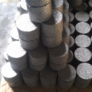
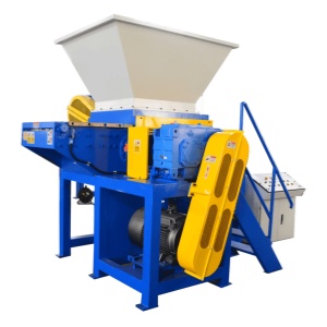
A metal baler, commonly referred to as a "scrap metal baler," is a mechanical device used to compress and package various types of metal scrap—such as scrap steel, iron, copper, and aluminum—into dense, compact bales. Driven primarily by a hydraulic system, the machine compresses the fed metal feedstock into uniform shapes, typically rectangular or cylindrical, facilitating more efficient storage, transportation, and subsequent remelting.
Hydraulic metal balers offer a wide range of applications across the recycling sector. Capable of processing scrap metal components of varying shapes and sizes rapidly and efficiently, these machines significantly reduce both time and labor costs compared to traditional manual baling methods, thereby enhancing overall productivity. As a result, they are highly favored by recycling and processing operations, including scrap yards, steel mills, and smelting plants, and are regarded as an essential piece of equipment in the scrap metal recycling industry for advancing the circular economy.
Structure and Components of a Metal Baler
In terms of structural configuration, metal balers are categorized into two main types: vertical metal balers and horizontal metal balers.
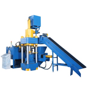
The primary components of a standard vertical metal baler include the following:
Hydraulic Cylinder
The hydraulic cylinder consists of a barrel, piston, and seals. It converts hydraulic energy into linear mechanical motion. When high-pressure oil enters the cylinder, it extends the piston rod, thereby driving the movement of the compression platen.
Motor
The primary function of the electric motor is to provide motive power. Serving as the power source for the entire hydraulic system, it converts electrical energy into mechanical rotational kinetic energy to drive the rotation of the hydraulic pump. The power rating of the motor directly determines the working pressure and cycle speed of the baler.
Hydraulic Pump
The main function of the hydraulic pump is to convert mechanical energy into hydraulic energy. Once the motor is running, the pump draws hydraulic oil from the reservoir, pressurizes it, and delivers it to the hydraulic cylinders and manual directional valve.
Oil Tank
The function of the oil tank is straightforward: it stores the hydraulic fluid while also serving to cool, settle contaminants, and supply the system with oil.
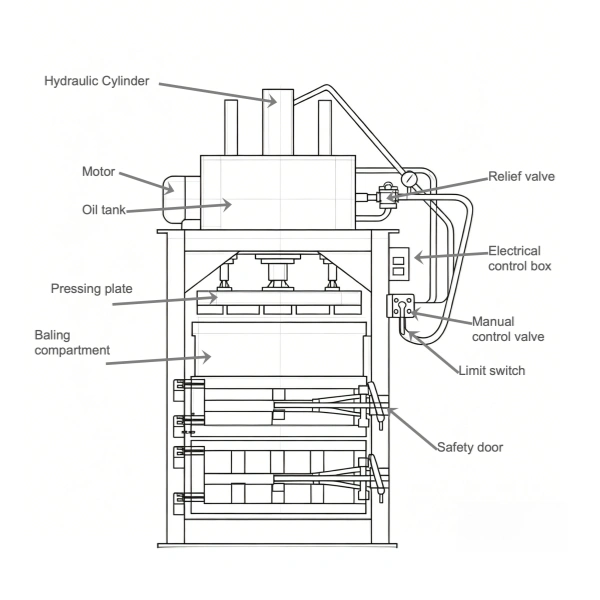
Pressing Plate
The platen is the force-bearing component that comes into direct contact with the scrap metal (e.g., aluminum turnings, copper sheets). Driven downward by the hydraulic cylinder, it compresses the charged scrap metal into a dense, compact bale.
Relief Valve
This valve is primarily used for pressure regulation and safety protection. Should the system pressure exceed the preset safety threshold, the relief valve automatically opens to divert oil flow back to the tank, thereby preventing hose rupture or pump overload. The maximum tonnage (compression force) of the baler is set by adjusting the spring tension of this valve.
Electrical Control Box
The control panel is responsible for receiving signals from limit switches and push-button commands. It controls the motor starter and the solenoids of the manual directional valve.
Manual Control Valve
The main function of the manual valve is to allow operator control over the direction and flow of hydraulic fluid. By shifting the position of the lever, the operator controls whether the hydraulic cylinder extends (feed/compress stroke), retracts (eject stroke), or stops.
Limit Switch
When the compression platen reaches its preset forward (compression) or return limit, it activates the limit switch. This immediately interrupts the control circuit in the electrical panel, stopping the motor or centering the directional valve to prevent mechanical collision and equipment damage.
Safety Door
This is a rectangular box constructed from heavy-gauge, high-strength welded steel plate. The platen moves within this chamber. Since the chamber must withstand tremendous lateral expansion forces during compression, the structural design and steel thickness must adhere strictly to safety standards; otherwise, a catastrophic failure and safety incident may occur.
Safety Interlock Guard
This locking mechanism is a critical safety feature, typically interlocked with a limit switch or safety relay. The electrical panel will only permit motor startup or cylinder movement when the guard door is fully closed and locked. This prevents the operator's limbs from entering the baling chamber during operation, thereby eliminating the risk of crush injuries.
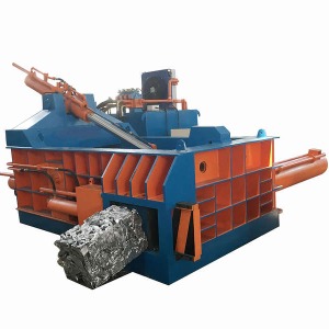
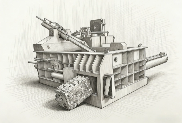
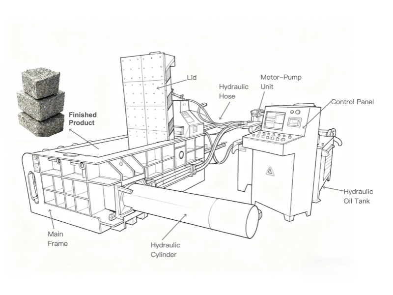
Main Components of a Standard Horizontal Metal Baler
The primary components of a standard horizontal metal baler are detailed as follows:
Main Frame
The frame serves as the foundation of the entire equipment, bearing and restraining immense expansion forces. Constructed from high-strength welded steel plate, it must strictly conform to safety standards. When the hydraulic cylinder drives the ram to exert extreme pressure on the scrap metal, the material generates substantial counter-force against all walls of the baling chamber.
Hydraulic Cylinders
The operating principle of the cylinders is fundamentally the same as in a vertical baler. The key distinction lies in the configuration: a horizontal metal baler typically employs multiple hydraulic cylinders working in coordination. These are dedicated to specific functions, including the main compression ram, side compression rams (if applicable), and the actuation of the lid/ gate opening, closing, and locking mechanisms.
Hydraulic Oil Tank
The function of the oil tank remains consistent with that of a vertical baler.
Control Panel (PLC Cabinet)
This control enclosure typically houses a Programmable Logic Controller (PLC). The PLC is responsible for processing push-button commands and precisely controlling the sequence, timing, and pressure of the various hydraulic cylinders, thereby enabling automatic or semi-automatic baling cycles.
Electric Motor
The operating principle is identical to that of a vertical metal baler. The motor's power rating directly dictates the flow rate of the hydraulic system and the load capacity of the pump, consequently affecting both the cycle speed and the maximum pressure of the baler.
Hydraulic Pump
Consistent with the vertical metal baler, the pump supplies high-pressure hydraulic fluid at a specified flow rate to the entire system, functioning as the "heart" of the hydraulic circuit.
Lid/Gate
The lid, often referred to as the "gate," primarily functions to enclose the compression chamber and withstand axial pressure. During feeding and compression cycles, it remains closed and locked, forming a sealed compression chamber in conjunction with the main frame. When the main cylinder executes the final extrusion stroke, significant counter-force is exerted directly against the lid; therefore, a reliable locking mechanism is essential. Upon completion of the bale, the lid is actuated by a dedicated hydraulic cylinder to open, allowing for the ejection of the finished bale.